GEOWIND · WIND TURBINE
See the built structure;
measure the wind.
GeoWind's triangular blade panels form a polyhedral rotor around a central vertical shaft inside a square support frame. This page uses the supplied build photo to explain the structure. Generation performance still requires measurement.
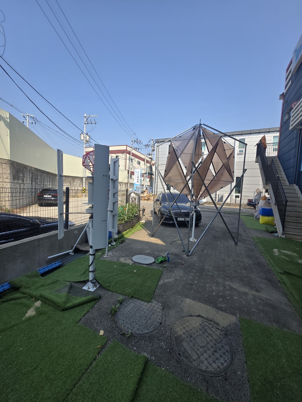 Supplied photo of the built structure
A visible structure
with measurable physics.
Wind applies force to the blades, turning the shaft and driving a generator. Even with the same generator, blade area, angle, speed and electrical load affect actual output.
For general vertical-axis turbine principles, see the U.S. Department of Energy overview. GeoWind-specific output still needs its own tests.
- 01 · Blades meet windWind direction and speed interact with blade size and geometry.
- 02 · Shaft and generatorTorque and RPM need to match the generator's load characteristics.
- 03 · Control and storagePower conversion, storage, protection and loads must be designed together.
A polyhedral rotor
inside a square frame.
On the right of the photo, you can see the corner support members, central vertical shaft and triangular panels of the rotor. The image shows the assembled form; it does not establish electrical output or efficiency.
- Fixed structureThe square metal frame supports the overall installation.
- Rotating structureTriangular blade panels form a three-dimensional rotor around the central shaft.
- What to measureRecord wind speed, RPM, electrical output and vibration together to compare performance.
A real rotor on display.
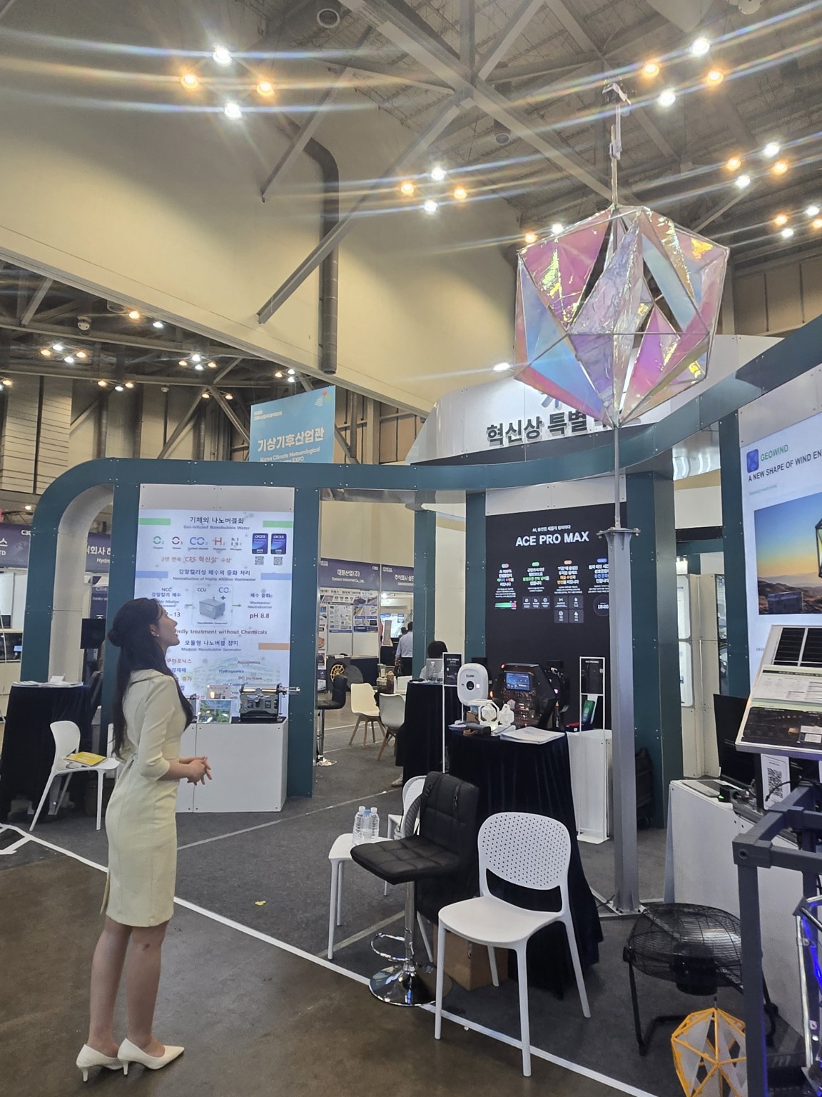
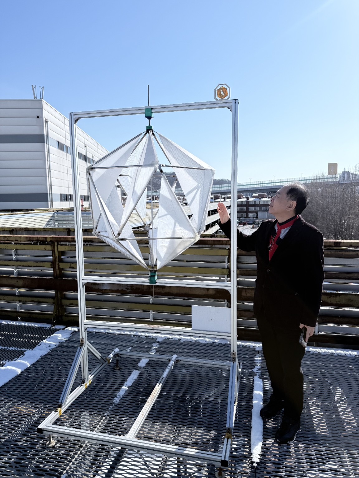
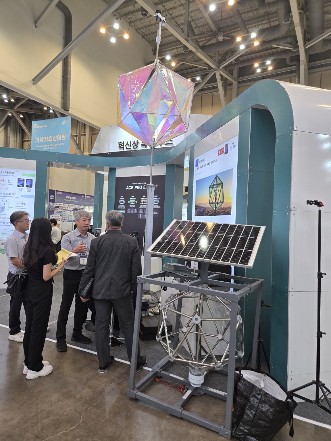
Photographs of the polyhedral rotor exhibited at the 2026 World Climate Industry EXPO and a separately built rooftop prototype. They document the form, not measured electrical output or efficiency.
As wind speeds rise,
available energy increases.
The theoretical power passing through a given area scales with wind speed cubed. These figures describe power in the wind, not GeoWind's measured electrical output.
Assumes air density 1.225 kg/m³ and an area of 1 m². Blade efficiency, electrical losses, cut-in speed, rated limit, turbulence and stopping controls are excluded. Method: U.S. DOE Small Wind Guidebook
76.6 W
1.0×
| Wind speed | Theoretical wind power / 1 m² | Vs. 5 m/s |
|---|---|---|
| 3 m/s | 16.5 W | 0.22× |
| 5 m/s | 76.6 W | 1× |
| 7 m/s | 210.1 W | 2.74× |
| 10 m/s | 612.5 W | 8× |
Compare five blade sizes
under the same conditions.
Creative & Wings proposes testing blade characteristic lengths of 0.8, 1.0, 1.5, 2.0 and 2.5 m with a nominal 1 kW generator. The generator rating does not imply 1 kW of actual site output.
Status: testing proposed and in preparation. These are planned dimensions, not measured output results.
- Power curve by wind speedRecord voltage, current and power under consistent test conditions.
- Start-up and stabilityObserve start-up, RPM, vibration, noise and stopping behavior.
- Wind at different sitesCompare conditions at sites with different heights, obstacles and turbulence.
- Operation alongside solarTrack wind and solar generation and battery charging over time.
CONTACT · CREATIVE & WINGS
Let's discuss testing
and deployment.
Share your intended site and test goals to begin a technical discussion.